Plan for Stable Micro-Geometry
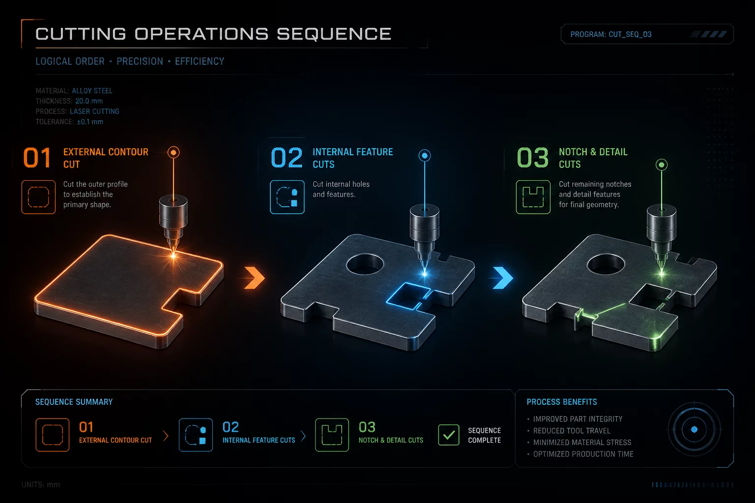
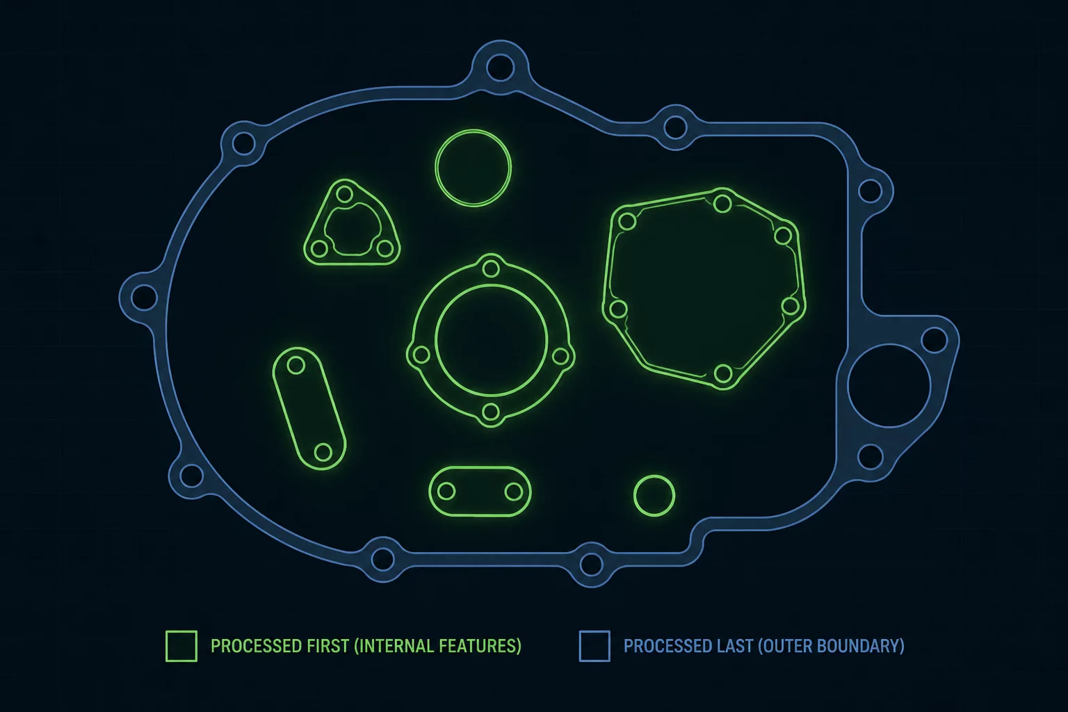
Internal cavities and delicate slots are processed prior to outer perimeter releases. The sheet remains locked to the honeycomb bed, preventing part tilt, focal blur, or collision during final travel paths.
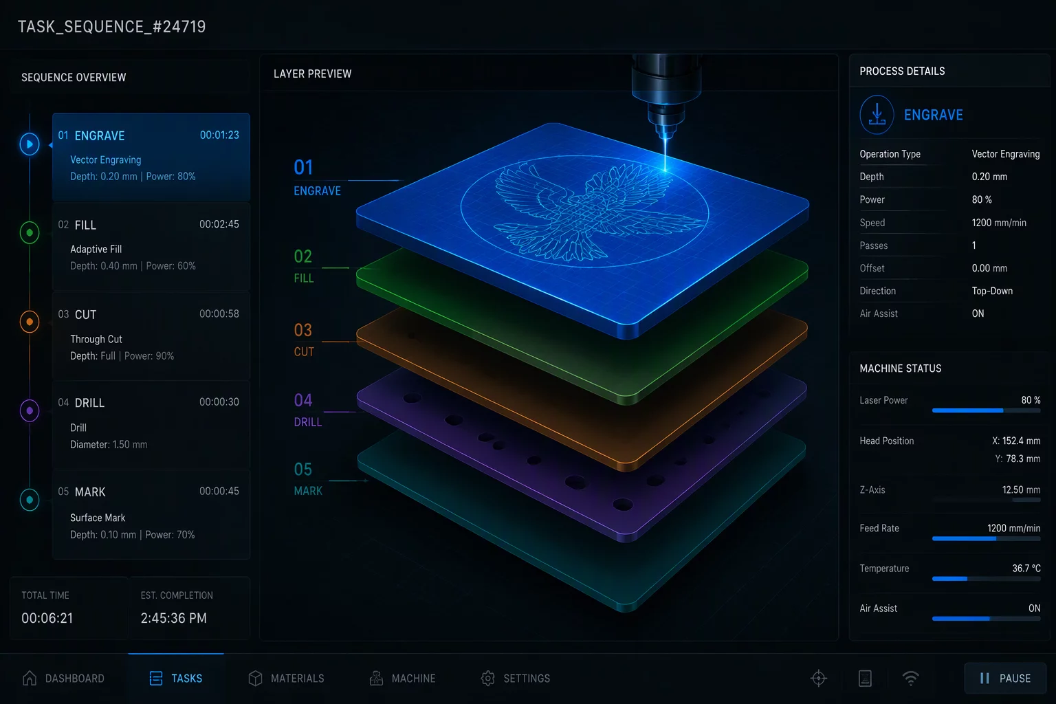
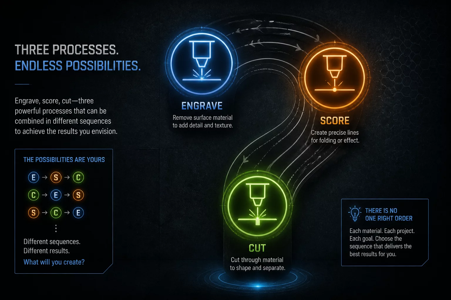
Study engraving, marking, cutting, sequencing, grouping, and layer-order decisions through visual run maps.
“What is each layer supposed to do before the job reaches the machine?”
Compare how planned toolpath sequence roles eliminate scorched corners, double-cut geometry errors, and fragile unsupported parts before sending jobs to production machines.
| Execution Stage | Typical Guesswork Approach | LayerRun Atlas Map Approach |
|---|---|---|
|
1. Layer Assignment & Roles
Initial artwork setup
|
Arbitrary Colors
Layers are assigned random palette swatches without standardized operational roles, leading to confusion between engraving fills and high-speed vector scores. |
Strict Functional Roles
Every vector element is mapped to strict semantic roles (Engrave → Score → Cut) with distinct airflow, speed, and focal tolerances defined before runtime. |
|
2. Toolpath Sequence Order
Machine path processing
|
Automatic Software Sorting
Outer perimeters frequently cut first, causing workpieces to drop, shift focal height, and tilt before internal raster engraving or detailed marking takes place. |
Inside-Out Deterministic Run
Pre-calculated execution hierarchy processes surface engraving first, small interior dropouts second, and final external perimeter cuts strictly last on firmly supported stock. |
|
3. Overlapping & Shared Geometry
Inter-part vector borders
|
Double-Pass Burning
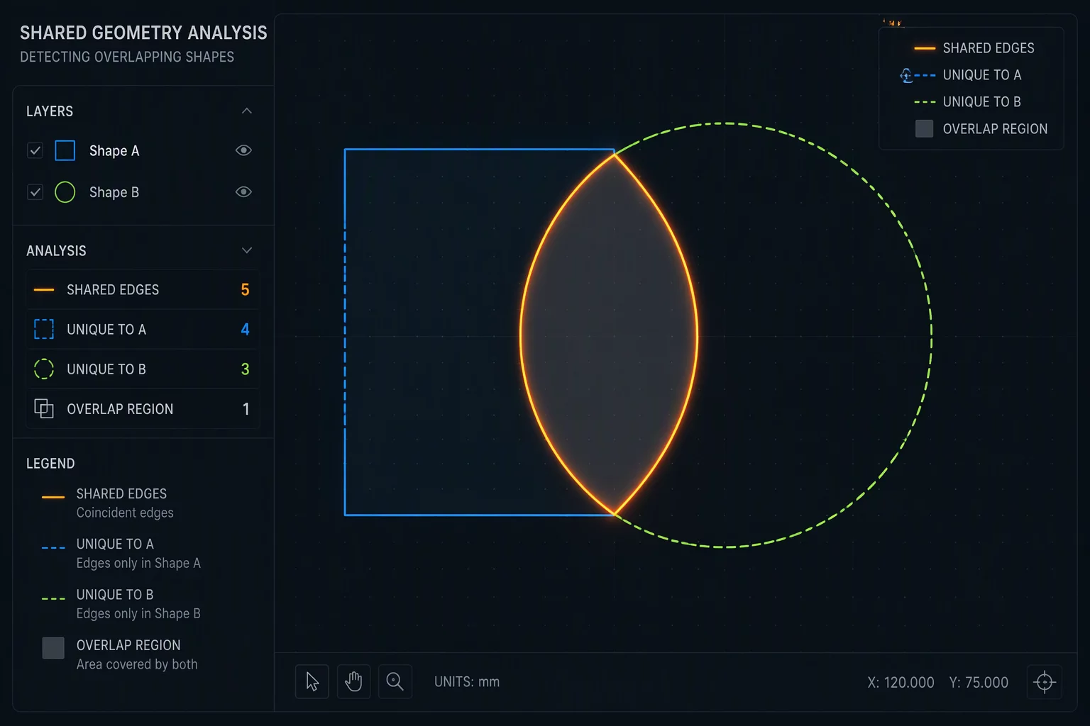
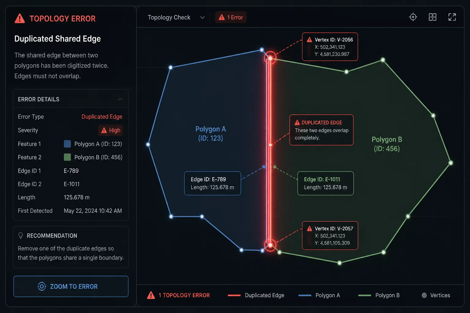
Shared bordering lines between adjacent parts are traced twice, creating heavy carbon buildup, heat deflection, charred kerf edges, and wasted runtime. |
Deduplicated Single-Line Paths
Shared vector nodes are unified into dedicated partition layers with single-pass optimization, preserving clean material edges and cutting total travel time. |
|
4. Multi-Material Proofing
Pre-execution verification
|
Trial & Error Scraping
Operators guess speed and power ratios on expensive stock without verifying air assist states, leading to charred acrylic masking or scorched plywood finishes. |
Visual Run Map Proofing
Complete multi-pass parameter validation occurs in preview mode against verified substrate standards, ensuring repeatable production outcomes without wasted inventory. |
Random palette colors without standard functional roles create confusion between surface engraving and vector scoring operations.
Explicit semantic layer roles (Engrave → Score → Cut) enforce airflow, speed, and focal settings before job execution.
Outer perimeters cut prematurely, letting cut pieces drop and tilt out of focus before interior rastering completes.
Inside-out deterministic hierarchy engraves top surface first, clears interior dropouts second, and executes outer cuts strictly last.
Shared edges are cut twice, multiplying carbon scorch marks, widening cut kerf tolerances, and wasting machine time.
Deduplicated single-pass shared boundary paths preserve clean edge profiles and reduce total cycle duration.
Blind machine runs without visual air assist checks result in scorched paper masking, melted acrylic, and ruined materials.
Visual layer verification in proofing mode cross-references tested parameters before the job ever reaches the laser bed.
Eliminate workpiece shift, edge scorch, and wasted stock by structuring operations into rigid, verifiable execution maps before beam contact.
Internal cavities and delicate slots are processed prior to outer perimeter releases. The sheet remains locked to the honeycomb bed, preventing part tilt, focal blur, or collision during final travel paths.
Engraving and vector scoring occur under uniform focal heights before cut kerfs compromise exhaust air velocity. Surface details remain crisp with minimal carbon staining or lens fogging.
Coincident lines across tiled components are consolidated into distinct single-pass vectors. This stops double-pulsing over shared boundaries, keeping kerf widths exact and preventing heat distortion.
Run Maps isolate layer hierarchy visually, letting operators catch unassigned paths, dormant guide lines, or inverted cutting logic directly on screen prior to controller transmission.
Specific assist pressure and duty cycles map to layer names rather than arbitrary color tags. Acrylic flames and char-prone plywood jobs receive proper solenoid triggers automatically.
Standardized vector ordering creates self-documenting project files. Any shop technician can load the layout, review layer sequence cues, and hit start with total certainty.
Lead Systems Architect
In laser manufacturing and prototyping workshops, the majority of ruined stock and optical head collisions trace back to a single issue: running vectors without an explicit visual sequence map. When operations overlap and order is left to chance, precision fails.
LayerRun Atlas exists to provide clarity before the laser head ever powers on. By breaking down multi-stage geometries into predictable, color-coded execution tiers—engraving first, scoring vector paths, and reserving perimeter cutouts for the final sequence—we turn unpredictable beam jobs into repeatable engineering runs.
Every guide, spec profile, and toolpath blueprint published here is tested rigorously on physical gantry setups to ensure total workpiece integrity from initial pulse to final drop.

Select a tailored engagement format to audit vector hierarchies, eliminate geometry conflicts, and standardize multi-pass sequences before job launch.
Comprehensive layer audit and custom Run Map generation for a single production-ready job or complex multi-layer nested assembly.
Continuous engineering support for workshops and makerspaces managing high-turnover job queues, layer presets, and speed-power maps.
Direct 1-on-1 technical diagnostic session to inspect cut order logic, troubleshoot burn defects, or streamline your layer hierarchy.
Currently selected: Ongoing Support. Fill in the details below to schedule your engineering session.
Verified layer order strategies and execution blueprints to eliminate job rework, burnt geometry, and unexpected cutting trajectories.
Prioritize raster fills before perimeter separation to maintain strict focal stability across unsupported cutouts.
Execute internal contours and slot features strictly before processing external boundaries to prevent part drop.
Deduplicate coincident path edges and optimize common cutlines to reduce cycle times and material scorching.
Organize multi-part nested sheets into ordered sub-clusters to control thermal buildup and nozzle travel distance.
Step-by-step diagnostic workflows resolving multi-layer conflicts, toolpath misalignments, and perimeter cut priorities.
Determining structural priority to eliminate piece shift and smoke staining during high-power cutting passes.
How unmerged redundant color layers double machine cycle times and cause material thermal distortion.
Diagnosing overlapping vector boundaries and implementing single-stroke common line cutting.
Toolpath nesting strategies ensuring loose fallouts do not disrupt beam focal distance during final perimeter drop.