Coincident Path Collisions
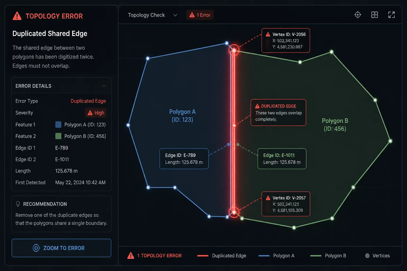
When vector geometries sit edge-to-edge on a nesting sheet, design software frequently retains individual closed perimeters for every single part. Placing two rectangular components flush against one another produces two coincident vector paths along their common boundary line. The laser controller faithfully reads both vector paths, executing the first part completely and then retracing that exact same seam during the second part cut.
This redundant second pass delivers concentrated thermal energy directly into an unsupported edge. In sensitive materials like 3mm acrylic, birch plywood, or thin MDF, the duplicate cut expands kerf width, ruins dimensional tolerances, creates excessive flashback charring against the honeycomb bed, and increases machine cycle times unnecessarily.
Resolution & Common-Line Nesting
Eliminating redundant cutting along shared seams requires restructuring how vector boundaries are grouped and converted before generating the G-code or sending the job payload to your controller. Rather than leaving parts as independent closed loops, apply systematic vector cleanup protocols:
- Execute automated node deduplication with a tight search tolerance (0.01mm) to scrub duplicate coincident lines across identical layer assignments.
- Deconstruct closed boundary loops into open polyline segments, deleting one overlapping seam stroke so adjacent components share a single cutline.
- Group internal shared cutlines into a dedicated preceding cut pass, ensuring shared dividers release before the final outer enclosing frame severs.
Executing true common-line cutting cuts material burn, halves the linear motion needed along shared seams, and prevents detached parts from tilting upward and colliding with the laser nozzle on a repeated pass.
Preview Traversal Verification
Always validate your toolpath timeline in your CAM preview window before initiating machine execution. Slowly drag the simulation slider across adjoining part boundaries and observe the virtual cutting head. The traversal indicator must cross every perimeter division exactly once, confirming that no duplicate vector strokes remain hidden within your layer stack.