Detecting Co-Linear Edges
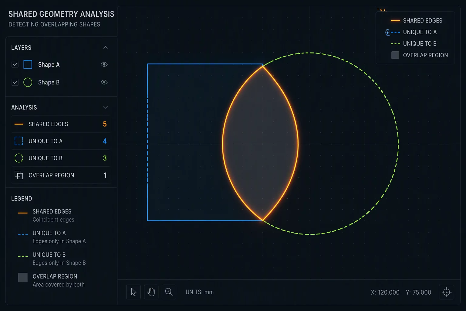
When nested geometric shapes abut seamlessly in CAD designs, overlapping line segments naturally develop along their shared contact boundaries. Standard vector software interprets every closed shape as an independent cutting path, causing the laser head to retrace the identical seam multiple times.
This duplication delivers double the required thermal dosage into a single narrow kerf channel. The material along that seam undergoes intense charring, structural weakness, and dimensional deformation. In delicate acrylics or thin veneers, this excess thermal buildup creates noticeable edge melt or ignition hazards.
Common Line Separation Strategies
Resolving duplicated geometry requires breaking closed perimeter shapes into independent line segments and reassigning shared dividers to a dedicated common-line cut pass:
- Isolate internal connecting dividers into an individual layer to execute single-pass slicing before releasing the main outer perimeters.
- Apply automated de-duplication tools in your CAM software to merge coincident vertices and eliminate invisible overlapping vector nodes.
- Sequence horizontal and vertical shared cuts sequentially, ensuring the workpiece retains solid bed registration throughout the cycle.
Executing shared partition cuts first preserves structural rigidity across the entire raw sheet. Once the internal common divisions are finished, the outer perimeter cuts sever the matrix without disturbing part stability.
Validating Toolpaths in Simulation
Before sending the final job to your laser controller, verify the motion sequence frame-by-frame using the preview simulation. Watch the laser focal head indicator closely as it traverses adjacent parts. If a seam draws bright twice or shows zero rapid traverse over an already severed channel, return to the vector canvas to sever the remaining duplicate segment.