
Mechanical Stability & Optical Registration
Executing laser toolpaths in the correct chronological sequence represents the single most important rule in multi-operation fabrication. When raw stock rests securely clamped or held by vacuum on the bed, it possesses full mechanical rigidity. Raster surface engraving demands intense bidirectional motion and generates thermal stress across the workpiece.
Placing heavy area engraving at the very beginning of the run ensures the substrate remains solidly connected to the scrap skeleton. If through-cuts execute beforehand, individual parts drop slightly into honeycomb voids or shift under assist airflow, causing subsequent text and graphics to lose focal height and register off-center.
Three-Phase Priority Hierarchy
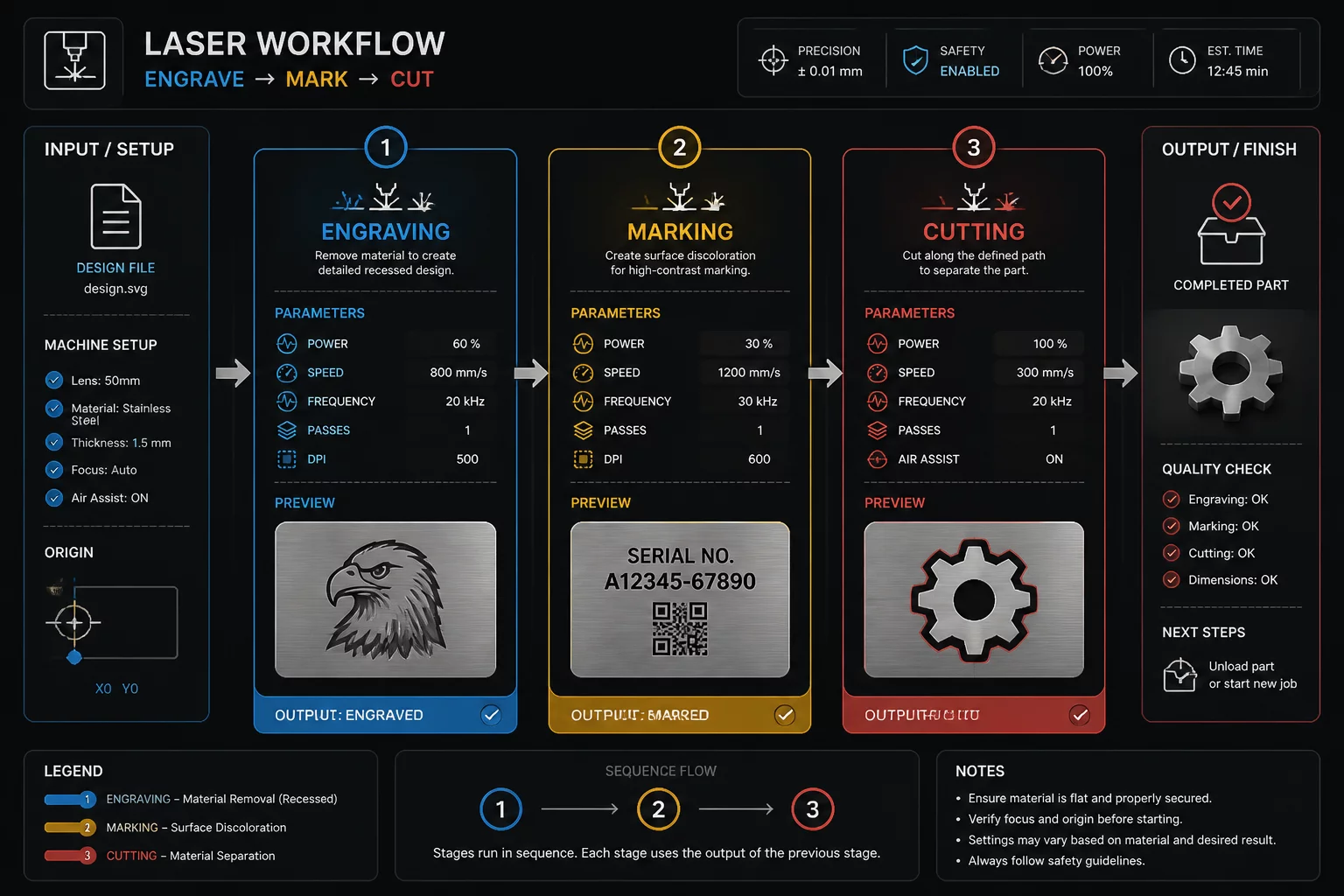
To make operation intent and sequence easier to review, this example organizes the layout into three distinct stages within the controller cut order list:
- Stage 1 — Raster Engraving (Fill): Large area textures and graphical elements are cleared first at high head velocity, using gentle air assist to prevent smoke staining across virgin sheet areas.
- Stage 2 — Vector Marking & Scoring (Line): Fine surface linework, alignment ticks, and fold indicators are scored at moderate speed without penetrating the bottom veneer.
- Stage 3 — Vector Through-Cutting (Cut): Inner mounting holes and internal cutouts are evacuated first, followed immediately by outer perimeter perimeter boundaries under maximum air pressure.
Reversing this sequence causes parts to vibrate freely during vector passes. Even microscopic movements of 0.1 mm destroy tight press-fit joinery and introduce visible stepping across fine decorative lines.
Kerf Clearance & Air Assist Balancing
Always simulate the compiled job toolpath using your CAM preview engine before pressing the hardware start switch. Verify that the layer order displays blue fills first, amber score vectors second, and red perimeter cuts last. Ensure that air solenoid presets switch dynamically between low pressure for raster preservation and high CFM jet velocity during final cut-through.