
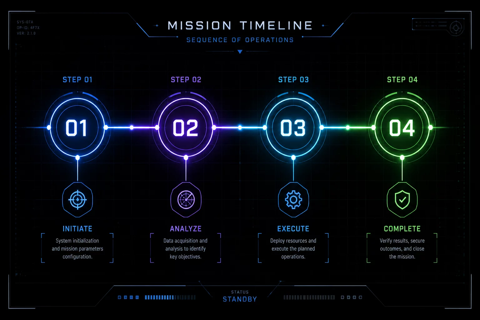
Hierarchical Logic of Machine Operations
Operation order defines the physical safety and geometric fidelity of every project sent to a CNC laser cutter. When setting up a multi-step design, software layer colors must map strictly to mechanical tiers rather than artistic preference. The workpiece retains its rigid factory alignment only while attached to the parent sheet. Once a through-cut breaks that structural bridge, air assist velocity, thermal warp, and gravity immediately cause subtle shifts that ruin subsequent engraving passes.
Treating layer organization as an immutable workflow timeline eliminates registration drift. High-speed raster scans place significant vibration on thin substrates, meaning fine surface details must conclude completely before vector contours begin penetrating the bottom plane. Maintaining this strict mechanical hierarchy is intended to help tight kerf tolerances and prevents ruined stock across both single prototypes and batch production jobs.
Chronological Pass Sequence: From Surface to Release
A stable toolpath follows four distinct chronological phases. Each phase performs a specific physical alteration without compromising workpiece immobilization until the final perimeter detachment.
- Phase 01 — Raster Engraving & Surface Relief: High-resolution raster scans engrave graphics and pocket fills across the fully clamped, uncompromised raw sheet.
- Phase 02 — Vector Scoring & Accent Lines: Low-power vector tracking draws sharp outlines, fold lines, and text borders without penetrating through the stock.
- Phase 03 & 04 — Internal Drop Slots & Outer Boundaries: Small mounting holes and nested internal apertures drop first, followed exclusively by outer perimeter contours.
In programs like LightBurn, ordering can be controlled by layer stack order, grouping hierarchy, or optimized path priority. Setting cut sequence strictly by layer order ensures that human-audited logic overrides automated path generators that might cut an outer perimeter before finishing center slot details.
Validating Execution Order via Simulation
Before firing the physical beam, load the interactive software preview slider to trace the simulated laser head path. Check that the virtual nozzle completes all solid fills, shifts smoothly to line markings, drops inner cut waste cleanly, and concludes only at the outer perimeter. If an outer boundary cuts prematurely during preview playback, adjust the layer stack position immediately. This two-minute simulation check consistently saves expensive acrylic, hardwood, and laser diodes from preventable crashes.